SergiusPaulus
Senior Member
AI has the ability to explain a schematic drawing. I am curious if AI could explain a free hand drawn schematic that is created based on electronic theories or suggestions.
This is an AI explanation of the attached image.
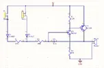
This circuit is a simple buzzer activation circuit using transistors. Here's a step-by-step explanation of the schematic:
### Components
### Circuit Operation
#### 1. Switches and Diodes:
#### 2. Resistors R1 and R2:
- R1 and R2: These resistors limit the current flowing through the circuit when S1 or S2 is pressed.
#### 3. Capacitor C1:
- C1: This capacitor acts as a filter to smooth out any voltage spikes or noise that may occur when the switches are pressed.
#### 4. Transistors T1 and T2:
#### 5. Resistors R3 and R4:
#### 6. Buzzer BUZ1:
- BUZ1: When T2 is turned on, current flows through R4 and BUZ1, causing the buzzer to sound.
### How It Works:
1. Pressing a Switch (S1 or S2):
- When either switch S1 or S2 is pressed, current flows through the respective diode (D1 or D2) and resistor (R1 or R2).
- The current through R1 or R2 creates a voltage drop that turns on the NPN transistor T1.
2. Activating the Transistors:
- When T1 is turned on, it creates a path for current to flow through R3 to the base of T2.
- This turns on the PNP transistor T2, allowing current to flow from the 5V supply through R4 and the buzzer (BUZ1) to ground.
3. Sounding the Buzzer:
- When T2 is turned on, the buzzer BUZ1 is activated and sounds.
This circuit is a simple way to activate a buzzer using either of two switches, demonstrating basic principles of transistor operation, current limiting, and noise filtering.
This is an AI explanation of the attached image.
This circuit is a simple buzzer activation circuit using transistors. Here's a step-by-step explanation of the schematic:
### Components
- S1, S2: Push-button switches
- D1, D2: 1N4007 diodes
- R1, R2: 100k ohm resistors
- R3: 1.2k ohm resistor
- R4: 47 ohm resistor
- C1: 0.1uF capacitor
- T1: BC547 NPN transistor
- T2: BC558 PNP transistor
- BUZ1: Buzzer
- Power Supply: 5V
### Circuit Operation
#### 1. Switches and Diodes:
- S1 and S2: These are the input switches. When either S1 or S2 is pressed, it allows current to flow through the respective diodes (D1 or D2).
- D1 and D2: These diodes ensure that the current flows in only one direction, protecting the circuit components from potential reverse voltage damage.
#### 2. Resistors R1 and R2:
- R1 and R2: These resistors limit the current flowing through the circuit when S1 or S2 is pressed.
#### 3. Capacitor C1:
- C1: This capacitor acts as a filter to smooth out any voltage spikes or noise that may occur when the switches are pressed.
#### 4. Transistors T1 and T2:
- T1 (BC547): This is an NPN transistor. When either switch is pressed, the voltage across R1 or R2 creates a voltage drop that turns on T1.
- T2 (BC558): This is a PNP transistor. When T1 is turned on, it creates a path for current to flow through R3, which in turn turns on T2.
#### 5. Resistors R3 and R4:
- R3: This resistor limits the base current of T2, ensuring it operates correctly.
- R4: This resistor limits the current flowing through the buzzer to protect it from excessive current.
#### 6. Buzzer BUZ1:
- BUZ1: When T2 is turned on, current flows through R4 and BUZ1, causing the buzzer to sound.
### How It Works:
1. Pressing a Switch (S1 or S2):
- When either switch S1 or S2 is pressed, current flows through the respective diode (D1 or D2) and resistor (R1 or R2).
- The current through R1 or R2 creates a voltage drop that turns on the NPN transistor T1.
2. Activating the Transistors:
- When T1 is turned on, it creates a path for current to flow through R3 to the base of T2.
- This turns on the PNP transistor T2, allowing current to flow from the 5V supply through R4 and the buzzer (BUZ1) to ground.
3. Sounding the Buzzer:
- When T2 is turned on, the buzzer BUZ1 is activated and sounds.
This circuit is a simple way to activate a buzzer using either of two switches, demonstrating basic principles of transistor operation, current limiting, and noise filtering.