Delta T, Helmholtz Variation

Einstein

Temporal Engineer
Messages
5,413
Thank you, @Einstein . Very informative and encouraging.

When I first received an HDR from Steven Gibbs, I placed a compass a various points around it to see how it would respond. Close to the end of the electromagnet, the compass would point away from the electromagnet, but in close proximity but at 45 degrees to either side of the end of the electromagnet, the compass spun like crazy - so fast it was just a blur and I cannot trust to guess what direction it was spinning in. Afterward I discovered that in this process the compass reversed polarity - it now points south. Oddly though, repetitions of making it spin has not reversed it back. With the HDR I assume this effect was caused by pulsed magnetic field. It may or may not be related to what you experienced with the sine/cosine coils, but comes to mind because of similar effect.

I would like to know how you generated signal at 90 degree phase offset from the other signal. That is my main stumbling block at the moment.

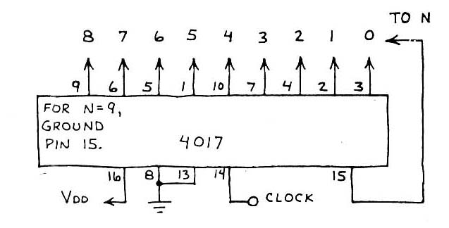
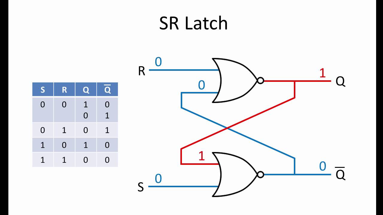
The sine-cosine signal was generated from a combination of integrated circuits. Most of my knowledge about IC's came from Radio Shack books. I used 3 basic IC chips. The 555 chip which I used to make the square wave pulses. It was ideal because it was cheap and allowed me to experiment up to a MHz of frequency. I fed the output of the 555 to the clock input of a 4017 CMOS chip. There is a schematic that shows how to configure the 4017 to a "count to N and then recycle" mode. I chose the count to 4 mode. The next IC was a 4001 CMOS chip. The 4001 chip has 4 independent gates in it. The circuit that was of interest to me was the RS Latch. I took the 4 output signals from the 4017 chip and fed them into two separate RS Latch circuits. Each RS Latch is comprised of two gates from the 4001 chip. Now comes the way I used the circuits to create a sine cosine square wave generator. The 4017 chip produces a sequential pulse from outputs 1 thru 4 then restarts the sequence. So I connected outputs 1 and 3 to the inputs of the first RS Latch. Then I connected outputs 2 and 4 to the second RS Latch. What this does is to create output pulses form one RS Latch that are 90 degrees apart in time with the second RS Latch. The outputs of the RS Latch circuits are connected to 4 Power Mosfets which in turn are connected to your 4 output coils. I would suggest you assemble this circuit on an experimental breadboard and play with it using LEDs to see how everything works at low speed.

circuit+counter+to+N+and+Recycle+by+IC+4017.jpg


maxresdefault.jpg
 

Sonix

Member
Messages
174
@Einstein , thank you so much! I'm not going to pretend that this isn't going to involve a learning curve for me to put it together, but I think I'm grasping the logic of how the circuit would generate 90 degree phase shift of the square wave and I have some 555 chips, just need to get the others, find some tutorials, and give it a go.
 

Einstein

Temporal Engineer
Messages
5,413
@Einstein , thank you so much! I'm not going to pretend that this isn't going to involve a learning curve for me to put it together, but I think I'm grasping the logic of how the circuit would generate 90 degree phase shift of the square wave and I have some 555 chips, just need to get the others, find some tutorials, and give it a go.

I would say this is more of an advanced level project. I never found any complete plans for a rotating magnetic field. So I had to absorb how to do it from what exists already. I would suggest learning how each IC chip works separately so you can visualize what you are actually doing. Also most 555 chips will only produce an output pulse up to around 200,000 Hz. But they are made in higher speed versions. My power supply was always from a 12 volt car battery. Also the Radio Shack Forrest Mims Notebooks series are very informative. The learning curve does get to a point where you get exposed to so much info that eventually you can start to devise and assemble your own gadgets. Also these parts are easy to get off eBay. And get spares of everything for inevitable mistakes.
 

TimeFlipper

Senior Member
Messages
13,705
Unfortunately 95% of your postings have been rhetoric, 5% are descriptions i.e Helmholtz Coils, Sine-Waves, out of phase Square waves, a Digitech Pedal, and a few frequencies...There has been nothing written that explains your reasons for choosing specific items and their relationships with each other that can begin to form an understandable coherent system....Your own imagination plays a large part in your writings and you are easily swayed by inconsequential writings (Delta-T Antenna T.E.C )....Above all you need to understand more about what you are trying to achieve, in other words you should learn to walk before you can run, because sadly you are very mixed up regarding time-travel...Einstein mentioned "advanced levels" and "learning curves" for you, i agree with him..

Our member Einstein had been experimenting for many years on time-travel and might still be involved with it in a "private matter", and myself has been experimenting for several years on creating a functioning, extremely stable, durable and physical//psychological safe system....Many people overlook the safety factor.....My own mentor regarding time-travel has been Preston Nichols for the past 17 years..
Fortunately, iam also an amateur radio operator like Preston Nichols was and i have been interested in electronics since i was a teenager, therefore i can grasp much of the electronic stuff he writes about easier..
 
Last edited:

Sonix

Member
Messages
174
...myself has been experimenting for several years on creating a functioning, extremely stable, durable and physical//psychological safe system...
I ask, as you have asked of me in this thread, "can you please explain to our members and my good self, what specifically is it that you are trying to create/construct, and what outcomes do you expect and how will you measure them?"

Please start a new thread for that so that discussion of our different projects don't get intertwined.

Please give "your reasons for choosing specific items and their relationships with each other that can begin to form an understandable coherent system". You've said that I am "very mixed up regarding time-travel", criticized that I "cannot even explain any theories or concepts as to why you chose your own design", and asked "...please also explain the model of Time Travel which justifies your concept plan." So please also explain the model of Time Travel which justifies your concept plan, as I would benefit from that as well.

You've expressed that these concepts are critical for experimentation (which is why I expect you can explain yours) and repeatedly ask them of me (which is why I expect that you, in good faith, will explain yours). If I don't have answers to some of these questions regarding my own projects, that would be because, as I've written before, we have different methods of operation. My sense is that you think I should already have a working understanding of Time Travel and only put together devices that I've already deduced will accomplish that and that I can explain why I expect they would accomplish that. But I work differently - I try variations on existing devices that have been reported to have effect and test to see if any of these variations do in fact have effect and, should any effect turn up, look at that as pointer to further research. I evolve devices dependent on results (if they ever occur), not bake them up from theory. I think of Edison reportedly trying 6,000 different materials for filaments before finding the one that met the criteria for the bulb he was working on. Edison didn't deduce the perfect filament, he rigorously tested possible variations until he hit on one with the effect he was looking for.
 
Last edited:

Mayhem

Senior Member
Zenith
Messages
6,745
One may say do not stop at trying to discover and achieve, let no one stand in your way though each can have opinions.
 

TimeFlipper

Senior Member
Messages
13,705
@Sonix I made all the relevant parts in my previous posting, iam not repeatedly going over the same grounds again and again, therefore i will make this posting the final one for you...You do not have any knowledge at all on what it is you are trying to create and the same is said for your own nonsensical "variations", and when you say that you Quote: ("work differently-i try variations on existing devices that have been reported to have effects and test to see if any of those variations do in fact have effect).....The design you were working from was that Delta T Antenna T.E.C. posting, that was ridiculous and in reality created no effects at all!!.....You cannot "test" anything because you have no idea what it is you are looking for!!...Its like someone trying to repair a radio with an oxy-acetylene cutter!!..

You are literally wasting my time because you know nothing of any relevance on the subjects you are writing about....95% of all your postings are waffle....I shouldnt worry about any of your postings clashing with mine!, and if you want to check out any of my previous postings you should know the forums where you can find them from....I will not be answering any questions you might put to me, and i will say now, if you want answers goto the Montauk series of books, or waste other knowledgeable members time with your irrelevant questions on topics you should study and learn about first!!.....This is my final posting on this thread, i expect at some point in time, nothing new will have changed, or have been learnt by you!....
 

Sonix

Member
Messages
174
@Einstein , the information you provided regarding your solution for creating square wave signal and 90 degree phase offset outputs using a combination of integrated circuits (much appreciated) prompted deeper searching about those chips and I encountered what might be a single chip alternative to be able to take an input signal and output a square wave and its cosine. There is mention of an IC (74AC74) in this page about a Software Defined Radio project that says it will take an input signal and output 2 signals at 1/4 the input frequency and 90 degrees phase apart.

"To generate a quadrature LO so that the signals are indeed equal and 90 degrees out of phase we have a simple logic IC called the Dual D Flip Flop, specifically the 74AC74. When a signal is applied to this IC the outputs are square waves 90 degrees apart and at 1/4 the input frequency. Therefore the input signal must be 4X the operating frequency."

They provide this picture of the chip's circuitry:

8390

Does this chip sound like a viable alternative?
 

Einstein

Temporal Engineer
Messages
5,413
@Einstein , the information you provided regarding your solution for creating square wave signal and 90 degree phase offset outputs using a combination of integrated circuits (much appreciated) prompted deeper searching about those chips and I encountered what might be a single chip alternative to be able to take an input signal and output a square wave and its cosine. There is mention of an IC (74AC74) in this page about a Software Defined Radio project that says it will take an input signal and output 2 signals at 1/4 the input frequency and 90 degrees phase apart.

"To generate a quadrature LO so that the signals are indeed equal and 90 degrees out of phase we have a simple logic IC called the Dual D Flip Flop, specifically the 74AC74. When a signal is applied to this IC the outputs are square waves 90 degrees apart and at 1/4 the input frequency. Therefore the input signal must be 4X the operating frequency."

They provide this picture of the chip's circuitry:

View attachment 8390

Does this chip sound like a viable alternative?

You could go down this path. But you will need 4 ouputs to run the 4 coils. A couple of inverters would give you the extra outputs. But might limit the output frequency due to the inverter time lag. Also TTL chips are not very compatible with other types of devices. When CMOS chips came along I abandoned all projects using the older TTL chips because of the interface problems associated with using them.
 

Sonix

Member
Messages
174
Ok. Thank you! I'll look deeper.
On one relevant (I think) point the design I'm working on differs from what you were doing with rotating fields - although it is 4 coils I am using, it is really 2 sets of coil-pairs-in-series, so I think I need only 2 outputs of signal.
 

Top