Opening A Real Dimensional Portals With Audio Frequency

TimeFlipper

Senior Member
Messages
13,705
Thank you and Happy New Year.
I was thinking of both:
  1. A Mobius Coil as the antenna (cut to frequency) connected to a transmitter (transmitting at 432 Hz). and
  2. A Tone generator (432 Hz audio) connected to a magnetic speaker, Aimed at the Mobius coil ant.
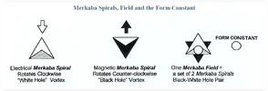
Two separate sets: a pseudo-Merkaba effect
Electric and Magnetic/Audio
With hopefully an "abnormality" in the middle. ;)

Looking at Number 2 on your list, using a tone generator set at 432Hz (sine..square..triangular wave?) and fed into a speaker, would cause a "pressure wave" onto the Mobius coil...Iam theoretically uncertain as to what effect you expect from that set up :unsure:...

If you decide upon building an RF transmitter on a frequency of 432Hz (good luck with that), you will be creating a "carrier wave" only....How would you make a Mobius Coil resonant to the frequency of 432Hz? :unsure:..

Please be aware iam genuinely trying to help you along with your projects...You are obviously aware that Tesla was able to destroy a small concrete building by using a resonant audio frequency, with only 2 to 3 watts output...I trust that you wont be inadvertently destroying your Mobius Coil in that process!! :eek: :D..
 

Doc 05

Active Member
Zenith
Messages
697
Looking at Number 2 on your list, using a tone generator set at 432Hz (sine..square..triangular wave?) and fed into a speaker, would cause a "pressure wave" onto the Mobius coil...Iam theoretically uncertain as to what effect you expect from that set up :unsure:...

If you decide upon building an RF transmitter on a frequency of 432Hz (good luck with that), you will be creating a "carrier wave" only....How would you make a Mobius Coil resonant to the frequency of 432Hz? :unsure:..

Please be aware iam genuinely trying to help you along with your projects...You are obviously aware that Tesla was able to destroy a small concrete building by using a resonant audio frequency, with only 2 to 3 watts output...I trust that you wont be inadvertently destroying your Mobius Coil in that process!! :eek::D..
Thank you,
Not sure of the sine or square (part of the experiment)
The pressure wave "should" pass through the coil.
The coil should be "resonant" by the length of the wire and tuning of the transmitter
If the transmitter is an old school crystal transmitter design, I should be able to match crystal to frequency.
Start low on output and increase from there.
Outcome: the Merkaba principle has always intrigued me; so every time I see something that "fits", I wonder how I would set up a table top experiment to get something to work.

8652

8653

Thank you again @TimeFlipper
I knew you would know. ;)
 

TimeFlipper

Senior Member
Messages
13,705
Yes iam fully aware of the crystals that were used for operating on a stable fixed frequency...For example, 7.1 Mhz was a classic amateur radio frequency for using Morse Code, and during the 1950s radio hams were using such crystals in their transmitters for simplicity, instead of building a variable frequency oscillator (VFO)...Crystals were also used for calibration of radio receivers....Radio Hams would sometimes change the frequency of the crystal by etching it, for example the 7.1Mhz crystal I mentioned could be etched to create 7.125 Mhz as an example...There was even a circuit created called "A rubber crystal" that could shift the crystals frequency very slightly!! :D...

To find the length of a resonant piece of copper wire in "meters" you need to divide the frequency in Megahertz into 300....I will explain..
The speed of light is 300,000,000 meters per second...I will use an amateur radio frequency of 10,000,000Hz (10Mhz)…Remove the 6 zeros from both, and we have the 10Mhz divided into 300, expressed as 10/300=30 meters of copper wire in length which is a full wave dipole...a half wave dipole is 15 meters in length, a quarter wave dipole is 7.5 meters length, a 1/8th wave dipole is 3.75 meters in length and so on..
.
To find the resonant length of an antenna for 432Hertz, we have to express it as 0.000432/300=approximately 695,000 meters for a full wave resonant antenna (providing my math is correct)...a half wave antenna is 347,500 meters in length, a quarter wave antenna is 173,750 meters in length, a 1/8th wave antenna is 86,875 meters in length and so on....It is necessary to know that if for example you chose the 1/8th wave length of copper wire, that is 86,875 meters, you still have to cut it into half as you would a half wave dipole...The "positive" side of the transmitters output goes to one half and the other half is known as the "ground" section of the antenna...Such antennas are made from straight lines in varying angles.

I believe you could possibly still keep reducing the length of the antenna, provided you keep dividing each length in accordance of how i set it out....Although i have no idea of how it would work, and by winding a suitable length of wire into a coil would not work as other factors such as inductance comes into play....Perhaps you might find some info on how to make a suitable "loading coil" for an end fed length of copper tubing of say 12 foot for example, operating on 432 hertz...Let me know how you get on with that will you? :)….
 

Doc 05

Active Member
Zenith
Messages
697
Yes iam fully aware of the crystals that were used for operating on a stable fixed frequency...For example, 7.1 Mhz was a classic amateur radio frequency for using Morse Code, and during the 1950s radio hams were using such crystals in their transmitters for simplicity, instead of building a variable frequency oscillator (VFO)...Crystals were also used for calibration of radio receivers....Radio Hams would sometimes change the frequency of the crystal by etching it, for example the 7.1Mhz crystal I mentioned could be etched to create 7.125 Mhz as an example...There was even a circuit created called "A rubber crystal" that could shift the crystals frequency very slightly!! :D...

To find the length of a resonant piece of copper wire in "meters" you need to divide the frequency in Megahertz into 300....I will explain..
The speed of light is 300,000,000 meters per second...I will use an amateur radio frequency of 10,000,000Hz (10Mhz)…Remove the 6 zeros from both, and we have the 10Mhz divided into 300, expressed as 10/300=30 meters of copper wire in length which is a full wave dipole...a half wave dipole is 15 meters in length, a quarter wave dipole is 7.5 meters length, a 1/8th wave dipole is 3.75 meters in length and so on..
.
To find the resonant length of an antenna for 432Hertz, we have to express it as 0.000432/300=approximately 695,000 meters for a full wave resonant antenna (providing my math is correct)...a half wave antenna is 347,500 meters in length, a quarter wave antenna is 173,750 meters in length, a 1/8th wave antenna is 86,875 meters in length and so on....It is necessary to know that if for example you chose the 1/8th wave length of copper wire, that is 86,875 meters, you still have to cut it into half as you would a half wave dipole...The "positive" side of the transmitters output goes to one half and the other half is known as the "ground" section of the antenna...Such antennas are made from straight lines in varying angles.

I believe you could possibly still keep reducing the length of the antenna, provided you keep dividing each length in accordance of how i set it out....Although i have no idea of how it would work, and by winding a suitable length of wire into a coil would not work as other factors such as inductance comes into play....Perhaps you might find some info on how to make a suitable "loading coil" for an end fed length of copper tubing of say 12 foot for example, operating on 432 hertz...Let me know how you get on with that will you? :)….
Thank You,
I know the antenna length for VLF is crazy; a submarine communications test antenna in Michigan was about 3 miles in length.
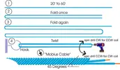
So I was looking at this Mobius Coil construction technique that may "compact" the physical dimensions.
How to wind a toroidal mobius coil
8658

And keep "dividing" the wavelength until I get under 1000 feet (1/2048 wave length ?)
A 10 pound spool of 22 AWG enamel magnetic cooper wire is 1000 feet. (ebay $80.00)

I need to look for the "shaving crystals" articles to see if I can find a thickness to frequency formula or chart.
Or can you "daisy chain" crystals (wired in series) to obtain desired frequency?

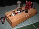
I found this transmitter kit on ebay and was thinking of this as a basic design:
CW transmitter
8659

I did find a possible source for the acoustic driver:
VLF/ELF generator

VLF10INS.pdf

Thank you for your help. ;)
 

Attachments

  • VLF10INS.pdf
    57.9 KB · Views: 16

TimeFlipper

Senior Member
Messages
13,705
Yes, submarines have been using underwater trailing wires for many years, originally operating between 15 to 20Khz...Aeroplanes use trailing wires too for communicating with submarines....The basic antenna has remained essentially the same for over 120 years, the exception being fractal antennas for UHF which are used in every cell phone that is now manufactured...The interesting part of those fractal antennas is that everyone of them has an ERP gain of between 3 to 5db...ERP stands for Effective Radiated Power, by which the gain of an antenna is compared to zero gain from a basic half wave dipole...For example, 100 Watts of power into a half wave antenna, is equal to 500 watts of Effective Radiated Power from an antenna with 5db of gain, expressed as 100x5=500 watts ERP :)..

The formula for working out the length of a "HALF WAVE ANTENNA" in feet and inches, is by dividing the frequency in Megahertz into 465...For example, 10Mhz is expressed as 10/465=46.5 feet...I will leave you with the equation for 432Hz (0.000432/465) ;)...You need to consult a company that sells crystals for fixed frequencies, there are a few on the internet, I already checked that out (y):)...
Iam not aware of any antenna being made from a Mobius coil, I did mention the problem with coils in my previous posting to you...However, you could check out "folded half wave dipoles" which help in small gardens and restricted space areas, but be aware of the distance required between each fold....

It was really good to see the old 6L6 tube in that transmitter, I recall that the early VOX AC30 guitar amps used to have a couple in them, you might have heard of a pop group called the Beatles, they used those particular amps back in the 1960s,i could never afford one ;):D..
The VLF generator looked awesome, but remember what Tesla did to that concrete building!! :eek::LOL:..
 

Doc 05

Active Member
Zenith
Messages
697
Hey Steve
Thanks for your comments on the start of my short story.
My design came about by a misspelling of the word portal as porthole on one of these threads; prompting me to ponder a “portable porthole portal” (say that fast 3 times).
  1. Most portal designs have no means of “tuning”; which is why the use of the HDR as a power/tuning source.
  2. Portal designs typically mention number of wraps or length of up-rights, but nothing about length of actual wire. Trying to keep with a Schuman’s resonance (and not have 1000s of feet of wire), I ran the standard antenna length formula on 432 Hz and came up with some “workable” (and affordable) lengths. My favorite being 1/4096 wave-length at 555.8 feet (also a 10 pound spool of 22 gauge copper wire is 1000 feet – 111.7 feet too short for the 1111.7 foot antenna).
  3. While researching the 432 Hz frequency and VLF/ELF antenna, I came across the Lithium Niobate crystal being used as a VLF piezoelectric antenna for emergency radios ( https://hackaday.com/2019/04/16/piezoelectric-antennas-for-very-very-low-frequencies/ ) and thought it would “enhance” the effectiveness of the HDR tuning by placing it in the witness well. I was able to find these crystals for sale as surplus laser crystals from the former Soviet Union on eBay.
  4. I’m still trying to incorporate a Mobius coil along with the Caduceus coil. In writing the “Disclaimer” intro for the “Pangaea Sucks” short story, I came across a photograph for a Crop-circle design of a Mobius coil (https://www.loohan.com/coilinfo.htm ), I’m attempting to measure the lengths of each arm of the crop-circle coil to determine the radio of arm length to diameter for the Mobius coil. If this is a “true” crop-circle it might give us a clue to the “proper math” for some of this madness.
Also if my theory is correct; crop-circles are used for time travelers/time line jumpers, to know when and on what time line they have moved to. Crop-circles don’t last (grow out) and with a simple program you could catalogue crop-circle designs and when they were made, the program would just match the design and tell you what timeline you are on (from the comfort of your UFO).
Soft copper tubing, 1 1/8 inch OD and 50 foot in length is available on eBay and could easily be filled with charcoal and/or crushed quartz to form a Mobius coil around and centered on the 55 gallon drum, along with a simple 2x6 wood frame for mounting the coil and holding the drum off the ground (steps?). Also, I need to determine if to or not, to “energize” the coil and how or see if there is any “induction” coming off the Caduceus coil.
  1. The electromagnet underneath with the coils above is an attempt to mimic a “Merkaba” effect, but I still have to think-through the coil and wrap directions. The magnet and the coil should “spin” in opposite directions (I have to check/call and find out which way Steve wraps his magnets). Or design/build a BAEM (Big Ass Electro-Magnet) with rebar and copper magnet wire; plugged in place of the HDR magnet (300 volts).
  2. I have identified a few natural vortexes on my property by using dowsing rods, but I need to confirmed them with a pendulum (is this a vortex that will transport me through time and space safely and return me to my correct or better timeline; correction – transport a chicken through time and space).
Ain’t Fringe Pseudo-Science great!
 

Inferno

Junior Member
Messages
85
I've never been convinced you can go to another dimension just by using sound.
I think there are a lot of factors involved and a lot of science we don't understand yet. It's supposedly specific frequencies combined with an electromagnetic field over a vortex that causes a portal, not just sound. I don't really know anything about it.
On the other hand-----anyone find it creepy that the video is removed?
I tried clicking it it said "video unavailable"
I believe this video turned out to be a fraud. But yeah, this happens to videos all over this sight. Anything older than a year seems to be removed.
 

Top