HAs anyone ever seen this schematic?
-
Like paranormal and time travel?
You are using an out of date browser. It may not display this or other websites correctly.
You should upgrade or use an alternative browser.🧲 Schematic 'Secret' HDR Schematics
- Thread starter tuvok50
- Start date
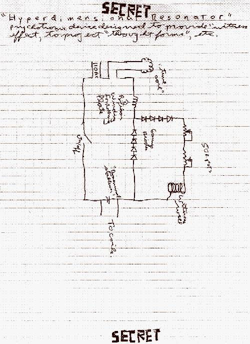
The schematic in question is quite questionable a few observations .
1. no mention is made as to how many turns should be made for the coil near the ac end also the gauge of the wire etc.
it is too vague
2. why not use one variable resistor instead of two ? also what is the value of the stated variable resistor ?.
3. I see an attempt at some kind of voltage multiplier but what are the values of the diodes in question ?
this schematic needs a lot more work and explanation .
Opmmur
Time Travel Professor
Here is Three Links to: Has anyone ever seen this schematic?
Time Travel
tt_hdr_pix
time travel linksLast edited:
Lumbergooz
Active Member
from electronic point of view; this is an oscillator with Tesla coil voltage amplification. it can be tested as HDR and if someone has electronics simulator, he can calculate coil details.
AlienWeaver
Junior Member
but the number of turns for the coil are missingThat schematic is some kind of voltage multiplier .
7.8Hz in the headband.
-
This site uses cookies to help personalise content, tailor your experience and to keep you logged in if you register.
By continuing to use this site, you are consenting to our use of cookies.