First of all I sent your schematic (both, the otherone as well) to pcbrapido two days ago, to let them etche some boards, with all the parts on it except the transistor and of course the coil, hence the question to maybe socket it.
What came back were the questions i posted.
WITHOUT THEY COULDN'T DO IT
you read that?
WITHOUT THEY COULDN'T DO IT
A PCB etching company said they CAN'T do it with your informations.
I put all the answers in a fritzing schematics and posted it to you for confirmation.
I even told you I wanted to get some boards made!
Then you latched out.
I actually wanted to get 20 boards etched (that was the minimum), 5 for me and 15 to donate whoever wanted one.
Accussing me all the time as a sock puppet is getting old.
I don't know who's trolling here, you just don't like it, if you are not right.
YOU posted a HANDMADE schematic so don't blame others for the mistakes.
Actually i used Veroboard, and NOT an etched PCB, for soldering the components onto, so you are wrong yet again ..
If you look closely you will see the Veroboard in my own DTG ..But of course you are going to reply by saying that your electronic wizards have also told you that my DTG wont even work using Veroboard, you are so predictable, so when are you going to get your "wizards" to come on here and try to back you up?..bring `em on ..
I thought you said you were quitting this thread, was your anger too much to hold back..
If you keep up with the arguments, Num7 will be forced to close this thread, so just chill out now .
I get the feeling you want to try and sell some of those DTG`s to get money for the corporation you are trying to create Mr A.L ..
Those are two pictures are of a Veroboard i found on the internet just for you, and you dont need to etch any copper boards anymore, they are a part of the past, and time wasting electronic construction..
I dont recall calling you a sock puppet, "after" i apologised to you on the DTG threads..
Im waiting for you to say that even the DTG i posted on here was found by you on the internet, so i will have a photo taken of me holding it up with a small poster saying, TimeFlipper from Paranormalis, togther with my two handheld transceivers plus my Yaesu FT-817nd all band transceiver....
Dear TimeFlipper,
I believe debunking is a normal thing here, you don't like it, I get that, your problem not mine.
Enough of your scientoligy tactics of ridiculing and confusion already.
You have obvious problems with reading my sentences, and keep putting words in my mouth.
Your accusation, that I am trying to get money out of this is offending,
even more when I think I wanted to donate 15 of those board to paranormalis, but you made that impossible.
I never said you didn't build this thing!!!!
I said you didn't follow your own schematics, and you can see that clearly in the photos you posted.
You called me 4x sock puppet since last week with no reason at all, out of the blue.
Just for information, I did read your posts before you changed them.
You insist I am a troll, you might look the definition up, but you can see usually my post have sources.
How about reading the Forum Rules?
1.) DECEPTION
You are lying in this thread from the beginning on.
Germanium transistors are not rare.
The best part of it: the vintage ones actually are quite used TODAY, that makes them the most sold vintage components available for use.
Yours isn't that rare either, even if you like to let us believe that.
There are millions out there, they just didn't sell that much to public back then, almost everything is on boards.
You know exactly what the designation of the transistor is, you have that good damn thing right in front of you!
Still you refuse to give the correct designation and call it on purpose M588 / SBT588 / 588 / SM588 / SBT ,so nobody can find it thus making it "virtually" a rare part.
After that you send everybody to that museum site to buy them, implying that it is cheap to buy 4 for 20$), knowing with the designation they could get it somewhere else.
To proof somehow what you say, before buying, you suggest to buy 2 books and two VHS! tapes.
20$ SBT (for me this would be on ebay: 2xSBT 2N588 + shipping =25$)
15$ coiling cable
40$ books
?$ tapes that don't exist
That is a hefty pricetag you put up there to verify a little what you say and build that thing.
The rest of the circuit is about 50 cents, for most 0$, cause everybody having something to do with this has those part lying around.
(look I have a perfboard too, hurra)
2.) SCHEMATICS
We might be on a paranormal site, but the moment you post a schematic you come right back to earthly stuff.
And a schematic is a schematic, it doesn't have additions, maybes or wrong designations of parts.
It's a definite plan to build something.
Yours is not, and it is like that on purpose.
There is so much stuff written on that piece of paper only to confuse people knowing less or nothing about circuitry.
Lets go step by step.
-There are ONLY THREE components on this schematic correctly drawn and designated.
The Battery, switch and coil
The rest have double numbering or Ohm signs one time there, one time missing.
If you start using units, use 'em the same way all over, but as an expert you know that, again all on purpose (MegΩ 10 10k 12 12k 1k5 470Ω).
You are stressing not to change anything so you should provide capacitor voltage (you do that with one but the important one you don't,none or both -> wanted confusion) and building material, as well as wattage of the resistors though not needed ususally.
(regarding "your don't change anything policy" in the thread you should provide it!).
-I already told you it's common practice to leave PIN 5 of the N555 out of the schematic but it means you put a capacitor there.
If you want that pin open you should draw that pin open (nobody leaves pins of ICs open in limbo, bad practice and causes error).
But I asure you, it is strange, looking at a capacitor (100uF 16V right of the coil line) for smothing out voltage, but you insist to leave PIN 5 open to cause false triggering.
-Like i said before, you have chassis grounds on the LED and on the bottom left. This is sooooo wrong with a plastic case but still you won't change this "mix up" of symbols, cause you like the confusion.
A kid who builds it like that, will end up turning it on, sees that the light doesn't go on and throws it in the corner cursing you to eternity.
He won't know that it's actually turned on and working. (working is relative here).
Your schematic calls for a metal case but you insist to use plastic.
-You state 10mA there over the 470Ω resistor, cause higher it'll blow your SBT, you say.
Output on PIN 3 is +-200 mA , you do the math.LOL
2N588 is good for up to 50 mA (and that is what they put there to be on the safe side), again a very confusing.
-The 150Ω value leading the SBT to ground has no resistor -> confusion.
(later you said to put it, wasn't it important not to change anything?)
This is all the earthly part of your schematic, my nephew knows to draw it better, he's 12.
We haven't even scratched the time distortion part yet.
-The Transistor on your schematic DOES NOT exist!!!
You put the wrong designation on purpose, and of course you won't change it, even if I pointed that out before.
3.) THE COIL
-Your schematic states clearly that the coils is a PI coil, still you keep calling it Tesla coil.
You say Americans call it a PI-Coil because it is round?
Do you think we are stupid or what?
A pie is called pi because it is round as well?
A PI coil is a PULSE INDUCTION COIL, but you know that, I am pretty sure of that.
They went with those to look for gold in 1890. The patent holder is American.
You imply, we have never seen a coil like that.
And it has been known for a long time now. -> straight lie again to add confusion.
What your coil diagram resembles is called a Magnetic Mirror Confinement.
You call that thing Tesla coil because Nichols calls the Helmholtz coils around the montauk chair Tesla-"something"-coils in the Mntauk book.
And overall, mentioning Tesla always adds a twist. Scientology likes that as well.
The only thing you say about this ominous coil is z=1000Ω. Thats it?
The second most important part on this design I just freeball?
And the unit for diameter is pipe? C'mon.
Later in the thread you say just do 4 coils each 250Ω (A+ for the math!)? What?
Then solder them together and add metal to a coil?
Just for your information, the distance between the coils is important to be the same with that kind of a coil, and needs to be half the radius of a coil, but who cares right. -> confusion again
4.)YOUR DTG
You didn' follow your own schematics and it is clearly visible in your image.
You didn't make the chassis connection and there is no SBT588 transistor on your board.
Sure I agree you have one there, but its not the one from your schematic, it can't be cause it does not exist.
Even more, your pic strongly indicates you are using a 2N128, but sure we can't read what it says, how convenient.
Look at the sockets of the 2N128 and the 2N588, really obvious!
How about turning around that SBT and take a pic?
Furthermore, it would explain why you have the problem with the "10mA" you feed the SBT. 2N128 only supports 5mA!
It should blow up right away switching this on.
I assume it doesn't happen that fast, cause you added a pound of solder to your circuit.
I have to tell you, you have some magic soldering skills going on there for a so called expert in electronics.
Ridiculous actually.
-You say this device is build around the theory of 400 MhZ whatever.
If I do the math on your circuit I get following output on PIN 3 of the IC N555:
POT 0Ω / R1 12kΩ / R2 10kΩ = 45Hz 15,25ms HIGH 6,93ms LOW
POT 1MΩ / R1 12kΩ / R2 10kΩ = 0,12 Hz 8,32s HIGH 6,93ms LOW
(HIGH=ON - LOW=OFF)
The N555 is in no way capable of reaching 400 something Mhz, you don't say that, but you strongly imply in the beginning.
5.)MOON+SCIENTOLOGY
One doesn't have to be bright to see the Scientology connection with Moon, Bielek and Nichols.
It is known that Scientology makes their money "forcing" people to buy books and tapes.
It is not a secret.
Montauk looks like a scientology stunt to sell books, nothing more and it became quite clear in the last couple of years.
But anyone can believe what he wants WITHOUT harming or scamming anyone of course.
I did talk to Mr. Moon yesterday, like you suggested
(I emailed, I wasn't in the mood to pay 30 bucks for a call and get scientology brainwashed)
The questions I sent were the following:
1.)Did this tape exist?
2.)If yes, would it be a problem to get a picture from the cover?
3.)If yes, where to get a hold of it?
4.)If yes, and YOU have copies, what is the price for them?
5.)Is there a schematic of the DTG that comes with the tape?
The answer was like expected:
So I make money with videos and I don't have a master?
I borrow my last copy, I have, to somebody?
The other questions he conveniently didn't answer, not because of time, nonono.
He sent me another email telling me something of being unstable and me talking to a friend of his.
The links in the first mail, as well lead to Scientology recruiting crap.
Your story is in no way verifiable and you know that, but you keep telling people where to verify it.
Everything always ends up on the transistor museum, or a site where you can buy the books.
BTW if you search "Delta Time Generator" only paranormalis shows up. LMGTFY
You can see there is only one person mentioning it everywhere...YOU.
That is impossible if this existed before you posted.
Not even the tapes are mentioned!
The internet does NOT forget.
Even less stuff like that.
Internet is a b**** @TimeFlipper and I would suggest to not post your name and infos publicly on the web, but it proofs you stalked Preston to talk about the DTG.
This link shows up on the search results from above. The last entry is very interesting. John Nichols Phone and Address | Zabasearch.com Free People Search - Page 3
There are so many lies in your posts, it is almost unbelievable nobody said anything so far.
But your usual tactic of ridiculing seems to work out pretty well.
Be careful with bashing the kids all the time, some could have real problems.
You belittle everybody that starts posting here, you don't care if its a kid 15 years old.
Ever thought about the consequences of your actions?
This is irresponsible for a grown up.
Change your schematic to a working, not confusing one and define the coil and the SBT correctly.
Otherwise this schematic should be taken down!
It leads to loss of money and it looks like a scam if you keep suggesting buying stuff from certain sources only.
I have to add as well, that you are way out of line, telling me I am forbidden to comment and
your threat, that if I keep posting there will be consequences with the administrator does not impress me at all.
I am not doing anything wrong.
You can see from the above that YOU do.
P.S.: You can post images of whatever transmitter or transceiver you want, it won't make your lies in this thread disappear.
Pushing buttons on a radio has nothing to do with this.
Your soldering skills proof you don't do that much circuitry anyway.
It's a thing of practice you know.
Oh dear are you waffling on again?..The soldering on my DTG is far better than you could ever achieve!...For goodness sake dont you try to solder any transistors, you will burn them out ..The schematic i posted stays as it is and your postings do not deter me from it one little bit..The DTG can be built into a metal case, but i preferred plastic, and i didnt need to change the earth symbol, as anyone helping someone to build the DTG would know it still meant a simple earth was required in a plastic box..
Youre rambling on again about the transistormuseum, and i left a link for one of our members, steve chiverton, to get in touch with you as he was looking for those transistors too...Look, go onto Ebay as our member einstein told you to and buy those transistors, if you really want to..
Although i believe that simple circuit for the DTG is too far out of your ability to make..
All you want to do is argue and argue and argue more, simply because you hate being proven wrong..and yes, Num7 will close this thread if you continue arguing much longer, he has done it before, because im sure he will at some time be pissed off with your incessant arguments..
The DTG is a very simple harmonic oscillator that works, i dont need to lie about that, it hardly costs the earth to make, and with a little bit of research from yourself, or what our members have already done for you, you will get the SBT`s that you obsessionally go on about...
I have explained the miniature Tesla coil to you, and if you cant follow my simple instructions on how to make it, thats your fault, iam not here to spoon feed you..
Please show me where it says a 2N128 base only "supports" 5milliamps.
The Tesla Coil of course is a Pi coil (I put that on the circuit diagram), but Tesla made 4 individual Pi coils, joined together by one single wire..
The 1000 Ohms is the resistance of the Tesla Coil and it acts as the "load" in the circuit...
Your assertion that only 3 components on the circuit diagram are "correctly" drawn and designated, graphically proves that you know absolutely NOTHING about components or their function within a circuit!!...
Lets start at the top left of the circuit diagram, Ok??..
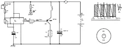
You will see R1 which is a variable resistor also known as a potentiometer, rated at 1meg Ohms, its the one with the little arrow on it..
Next one down is connected to R1 and is a standard resistor, rated at 12k or 12,000 ohms...
The next one down R2 is another resistor, rated at 10K which is 10,000 Ohms...ALL resistors are defined in Ohms..
Still going down, we see the Electrolytic Capacitor C1 which is valued at 1 microfarad (yes it should read 16 volts which i stated earlier)..The top part of it is the Positive side (+) and the other end of it which is in black, shows the Negative side (-)...That particular section is known as the R/C circuit, (Resistor Capacitor), which forms the part of the DTG`s tuning circuit..
Then we see the IC555, which is an integrated circuit, the signal from the R/C circuit is fed into it, and stable square waves come out of it, through R3 which is a resistor rated at 470ohms, and takes the current coming from the IC555 down to10ma (10milliamps), to protect the base of the SBT588, and also help battery consumption..
Now take a look back at R3, and directly above you will see D1 which is an LED (Light Emitting Diode.. R4 is resistor rated at 1k5, which is 1500 ohms, and goes down to the LED..
Next along the top row you see the symbol for the Tesla Coil, or Pi Coil if you need to be pedantic...that is fed into the Emitter part of the SBT, and the collector of the SBT goes down to Rx which is a Resistor rated at 150 ohms...To the right hand side of that you will see C2 which is also an Electrolytic Capacitor valued at 100 microfarads and rated at 16 volts, with the positive side of it is taken to the positive voltage (+) and the negative part of it which is in black, goes down to the negative part of the voltage..
Then on the top part you will see SW1 which is a single pole single throw on off switch...Finally on the right hand side you see the 9 volt battery...All the data i have explained to you about the components is 100% accurate, which can easily be verified
Should anybody have needed any help from me in the construction of the DTG, all they had to do was ASK..There has been a few requests from members that you can see and they were answered, also there has been over 6000 hits on the DTG, and sods law states that a few newer electronic minded members would have asked me more questions..
I have proved beyond any doubt that you are a LIAR!!, when you quoted my circuit diagram contains only 3 components that are "CORRECTLY DRAWN AND DESIGNATED"....Iam taking this further!...
Can you show me where i was supposed to have called you a sock puppet 4 times?..I think your paranoia is running wild, if they were there why didnt you high-light them?
That 4 lies from you..
Can you also show me where i was supposed to have said that SBT`s are rare?, i cant find one posting where i said that...thats 1 more lie from you..
You are VERY obsessive over names such as, Tesla..Bielek..Moon..Nichols, all of them supposed to refer to Scientologists, get a grip on yourself man ..what have they got to do with me??..Do you imagine iam a one of them, trying to convert members of Paranormalis into that cult?
And now iam supposed to be John Nichols am i?..I must check out my birth certificate to see if youre right ..I did check the link you kindly left us for that John Nichols, and the nearest to me was 70 years old same age as me, but living in Denver US!!!..FYI i live in the UK, infact all the John Nichols on your link come from some part of the US, so great research from you ..You have seriously "lost the plot" ..
It was YOU who brought up the idea that the Americans were responsible for using the term Pi coils..not me..show me where i supposed to have said that.. 1 more lie from you..all the time is lies lies and more lies from you..
Its very sad to see a member like yourself who is so full of hatred, and all over a very simple oscillator circuit which you obviously dont fully understand..
I have already told you that i have DVD copies of the VHS tape that Preston NIchols made, which included the DTG, and i will happily send one of them to our Administrator, Num7 to view for himself...But will you jump to the conclusion that he is part of a conspiracy regarding Scientologists too? ...
And finally, contrary to your statement, the only pin numbers ever shown, are those that are connected to something FACT...and notice on this schematic how the number 5 pin on the IC555 is NOT shown!..Just like on the DTG schematic that you argued and lied about!!....
hrough R3 which is a resistor rated at 470ohms, and takes the current coming from the IC555 down to10ma (10milliamps), to protect the base of the SBT588, and also help battery consumption..
There is a spacer for a Resistor, no resistor set at all. Isn't that what the perforated line means ,sir?
And now iam supposed to be John Nichols am i?..I must check out my birth certificate to see if youre right ..I did check the link you kindly left us for that John Nichols, and the nearest to me was 70 years old same age as me, but living in Denver US!!!..FYI i live in the UK, infact all the John Nichols on your link come from some part of the US, so great research from you ..You have seriously "lost the plot" ..
Scroll all the way down and for a change, try to read.
I will not post a picture here cause it wouldn't be right you posted your name there.
It's pretty obvious who you are and where you live, you are posting it all over the net, hence the advise not to do it, but thats not my problem either.
It was YOU who brought up the idea that the Americans were responsible for using the term Pi coils..not me..show me where i supposed to have said that.. 1 more lie from you..all the time is lies lies and more lies from you..
Number 6 is the miniature Tesla Coil, showing construction method on the right hand side...Basically its 4 coils all separated from each other (Americans call it a Pi coil as it is wound onto 360 degrees...
And finally, contrary to your statement, the only pin numbers ever shown, are those that are connected to something FACT...and notice on this schematic how the number 5 pin on the IC555 is NOT shown!..Just like on the DTG schematic that you argued and lied about!!....
I said if it is not shown you should put a capacitor there or you will get false triggering, and it doesn't make sense having .....blabla you won't read it anyway.tssss https://www.electronicsclub.info/555timer.htm If electrical noise is likely to be a problem a 0.01µF capacitor can be connected between the control input and 0V to provide some protection.
You did the same thing years ago here is a sample:
This is an example of your spamming 2006.
Absolutely unrelated page : Buddah's Dial-A-Hit
You are VERY obsessive over names such as, Tesla..Bielek..Moon..Nichols, all of them supposed to refer to Scientologists
Tesla? Never said that that is hilarious....Moon and Bielek sure did Nichols lol no way, nutcrack.
Did you read Moons books?
I'm a lot longer around than you think.
And I am tired of this promotion, most of all because of teenagers and youngsters reading your stuff and take it for real without doubting it, storming to buy 15 books 20 bucks each.
How about that pic of your "SBT588" in your box.
Or make a picture from the original schematic, can't be that dificult.
That'll shut me up very quick.
Won't happen i guess.
I understand that circuit pretty good, those parts in the pic i posted are mine not a pic from the internet
You base everything you say on a guy named Preston B. Nichols, I guess i have to write a little something so everybody can make their own decision.
I remember him posting on a board back in 2000 that gave a pretty good picture of his level.
And you really need to stop putting words in my mouth and attack everybody who is not your opinion.
A man in your age should be able to do that.
For the record I don't think at all you are one of them.
I will allow you to continue with your ramblings, i cant even be bothered to read your last posting, as iam bored with your paranoia, obsessions and litanies of lies..
You must see yourself as the lone paranoid obsessive Scientologist Hunter Of Paranormalis, you really need to get out more ..
I will now prepare the Space-Ship ready for Moon and Nichols and the rest of the scientologists to go onto when Armageddon happens ..
Have a great time in your fantasy world, toodle pips Mr A.L.Heka ..
Let's not bash Scientology. Despite Tom Cruise being a nut-job, I liked his work in that film Edge of Tomorrow, even if he's not a good or nice person. Plus, you must admire the marriage of science and religion as it creates a new-age cult which has a hand in many celebrity lives. I am truly fascinated if the founders truly believe what they peddle, or if it's an entire facade for monetary gains. My only concern with Scientology is that it has no apparent underlying basis of truth to it, whereas mainstream religions do, despite their abhorrent contradictions.
I used 30swg which is about 28awg in your definition..it was wound onto a hollow half inch piece of plastic tubing (air coil)
As you can see from the diagram there are 6 coil spacers, separating each of the 4 coil windings
As you know this is a very simple oscillator, and the coil impedence is measured in ohms
The heart of the device is the Surface Barrier Transistor which is called the SN588, this being useful for AF IF and RF purposes
This semiconductor has Quantum Tunneling properties, and hopefully can still be obtained from the transistor museum which you can locate on the internet....The whole circuit including the case can be purchased for less than $10, as i know that you have lots of components already at your place
This site uses cookies to help personalise content, tailor your experience and to keep you logged in if you register.
By continuing to use this site, you are consenting to our use of cookies.
 ..
..") ..But of course you are going to reply by saying that your electronic wizards have also told you that my DTG wont even work using Veroboard, you are so predictable, so when are you going to get your "wizards" to come on here and try to back you up?..bring `em on
..But of course you are going to reply by saying that your electronic wizards have also told you that my DTG wont even work using Veroboard, you are so predictable, so when are you going to get your "wizards" to come on here and try to back you up?..bring `em on 

") .
.") ..
..


 ..
..