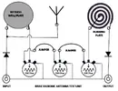
I dont think psychotronics stuff belong in the area of Electromagnetic Waves (Radio Waves), as there were no written frequencies on any of the diagrams i looked at...You said in your previous posting to me you wanted to keep things simple...Thanks; I wonder what the length is on these ant. and what freq. would one use to determine that (and if it matters in this application).
One of the documents I came across was Radionics Labs: Psychotronics 101 (see attached pdf)
Psychotronic Lab Journal Vol. 1 Published
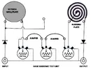
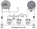
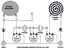
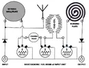
It has an interesting and insightful chapter on the "Psychotronic Application of Electronic Components"
This chapter answered a lot of questions I had on the radionics "off-label" use of electronics.
As this whole area is considered "pseudo-science", radionics could be labeled "pseudo-electronics".
After seeing your post I was reminded of the "learn electronics kits", with their peg boards, bags of components, and templates.
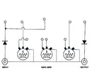
There fore, I propose the Radtonics Research Basic Board: Learn Psychotronics at Home Kit
Hey Kids , want to amaze your friends, trouble your parents, and obtain unlimited other-worldly power!
Order your kit today.")
Therefore i suggest you construct some shapes, similar to those i sent you, and start off by using different lengths of wire and write down anything significant that happened to you while connected to each coil...Keep us all informed of your progress please
") ..
.. ..
..