🧲 Schematic John Bajak Flux Capacitor

I’m trying bajaks flux capacitor as a stepping stone to the arduino flux capacitor as a way to tie things over. The wires were soldered together and I am waiting for the capacitor to come in the mail. Of course the arduino technology will take work and the nano one will be brought first since it is suitable for my computer and my budget.
 

Attachments

  • image.webp
    image.webp
    1.2 MB · Views: 9
There it is. Modified Bajak flux capacitor. Hopefully my beloved friend Tony can give me a nine volt battery for it. I’m working on creating a business selling calligraphy so I can get my arduino nano when I have enough.


Later, they did not put the sockets right on my battery. So I taped it together and turned it on. It works on emitting the sound and it appears that I traveled from 5:01 to 5:49 time on my iPhone.
 

Attachments

  • image.webp
    image.webp
    836.8 KB · Views: 10
Last edited:
Plugging the ASCIi version of the schematic into ChatGPT it displayed this response. Since GPT can analyze images you can upload any drawing to get various results.

This ASCII diagram represents an electrical circuit. Let's break down the components and connections:

1. S1: This seems to be a switch.
2. B1: This is likely a battery or a power source.
3. G1: This symbol appears to represent a ground connection.
4. G2 and G3: These are additional ground connections.
5. P1: This could be a potentiometer or a specific component labeled P1.
6. C1: This may be a capacitor.
7. The lines with /\/\/\/\: These represent resistors.

### Connections:
  • S1 is connected between two points in the circuit, leading to B1 on one side and G1 on the other side.
  • B1 is connected to the ground at the bottom.
  • G1 is connected to the top ground.
  • C1 is connected in parallel with P1.
  • G2 and G3 are grounding points connected to different parts of the circuit.

This circuit could represent a basic electronic circuit with resistors, a capacitor, a switch, and grounding connections. The exact function of the circuit would depend on the specific values of the components and how they interact when powered.
 
Hopefully we will have someone making the capacitor and successfully working as is said to. I'm much interested in teleportation machines though. anyone with good information on how to make the units?
 
This is a document I've put together a long time ago but never got to finish and post. It aims at being an all-in-one reference for the Flux Capacitor. Designs, improvements, feedback/testimonials, and more. We're attempting to come up with the best, most reliable parts and schematics as possible.

What is the Bajak Flux Capacitor?
The John Bajak Flux Capacitor often called Flux Cap or fluxcap, is a small time travel device. It is often mentioned alongside the HDR, Sonic Resonator and other small devices. It's a design that showed up on the old KeelyNet BBS in the 1990s. It's available on a very old website, called Amasci, which is linked at the end of this post. The Flux Cap schematics are available over there, as well as a few old forum posts from the late 90s and early 2000s that share some information about it. We have an on-site copy of the original Bajak file, as a backup for future reference.

In the document, the creator explains how he came to build it by accident, and how it could potentially be used for time travel. He even mentions the possibility of attaching it to a car, in order to create a time travel vehicle. It gets pretty technical towards the end, you'll see.

Here are 2 links to the original document:
John Bajak FluxCap Document (Paranormalis): John Bajak Flux Capacitor Time Travel Circuit
John Bajak FluxCap Original Document Location (Amasci): http://www.amasci.com/freenrg/bajak1.txt

The FluxCap is supposed to emit some sort of small temporal field (temporal flux) that would alter the rate at which time flows. It would, for instance, slow down or accelerate a watch by having it oscillate between past and future.

Quote from John Bajak:


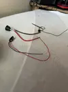
View attachment 12555

Parts List and schematics
B1 27 volt source
C1 1200 uF 50V electrolytic
P1 Piezoelectric transducer (273-073) (value uncritical)
S1 Charging switch (SPST)
G1 25-ohm rheostat (future control)
G2 1M-ohm potentiometer for past control
G3 Switch (SPST)

Transcriber's note: I don't know whether G1 and G2 are really supposed to be a rheostat and a potentiometer, or both rheostats, or both pots. He refers to two rheostats elsewhere, and I was just going to call them pots until I remembered that rheostats would have some inductance.

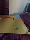
View attachment 12556

How to build the Flux Cap
We don't have building instructions at this point. Suggestions welcome.

Does anyone have schematics others than the one above? Actual schematics that are not in ASCII would be greatly appreciated.

How to operate the Flux Cap
The information we have as to how to operate the Flux Cap is as follows:


We encourage anyone who knows more about the Flux Cap to get in touch and share what they know. For instance, what do the above instructions do? Do they deal with the past? The future? How do you know which way the device is set to?

Links of interest
John Bajak FluxCap Document (Paranormalis): John Bajak Flux Capacitor Time Travel Circuit
John Bajak FluxCap Original Document Location (Amasci): http://www.amasci.com/freenrg/bajak1.txt
Report of Unusual Phenomena page, containing info about the Flux Capacitor: Report your Unusual Phenomena: experiment reports

Bajak Report File: John Bajak's Flux Capacitor Report File
Modified Versions of The Flux Capacitor: Schematics - Modified Versions of The Flux Capacitor
Discussion about the Flux Capacitor: Discussion About The John Bajak Flux Capacitor
Bajak Wolf Flux Capacitor: Bajak Wolf Flux capacitor
The danger input on the Bajak in the linked notes, as the test subject briefly expierence an atomic natured fire to himself withoput heart, is there may be lack of collumnation concerning proposed personal ujse with this device. The best test model in myth are the Vorgon's of 'Captains Holliday' episode of Star Trek TNG. Briefly put why their model would work per chance and ours does not, is that the episode use captures the subject using it with complete captured digital information, to where actually use has little.

As I said before, a reprogrammed Sam Sung Galaxy cell phone plus a data store from a Raspberry Pi minicomputer, with a coper plate, or some other style of plate to the body, then the Bajak circuited in there somewhere may be better & safer intended use.

If there would be such beings, they would be seven hundred or so years based in the future.

Remember the first field use of the semi-Bajak circuit, was to make a paperclip struck between the antenna & power mains of a stereo radio disappear. If this segment of time is from A to be, then somewhere along that line which carried the load, has to be improved for the subject that the circuit will carry? Thank you https://i.pinimg.com/originals/db/7f/1d/db7f1dcec3a706327d8a96e5a7c20630.jpg
 

Top