Einstein
Temporal Engineer
As some of you may know, I've been working on building a Hyper Dimensional Resonator. But I'm not quite satisfied that I have it correctly reproduced so far. I have some pictures to show my progress so far.
http://www.fileden.com/files/2006/7/30/148042/100_0247.JPG
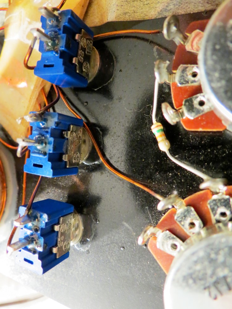
In the first picture you'll notice I color coded the plugs on the electromagnet connections so that the electromagnet produces a north pole field.
http://www.fileden.com/files/2006/7/30/148042/100_0248.JPG
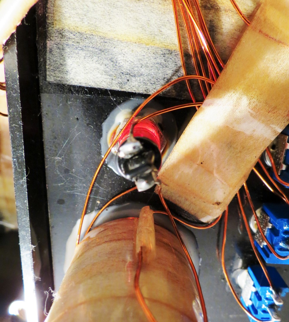
In the second picture I used a strain relief where the cord goes into the case. Also the cord itself was just an extension cord with a molded plug on the end. I just cut off the receptacle end and discarded it. This was cheaper this way because the extension cord was only $2.00 as opposed to $4.50 if I purchased the cord and plug separately as Steven Gibbs does with his design.
http://www.fileden.com/files/2006/7/30/148042/100_0250.JPG
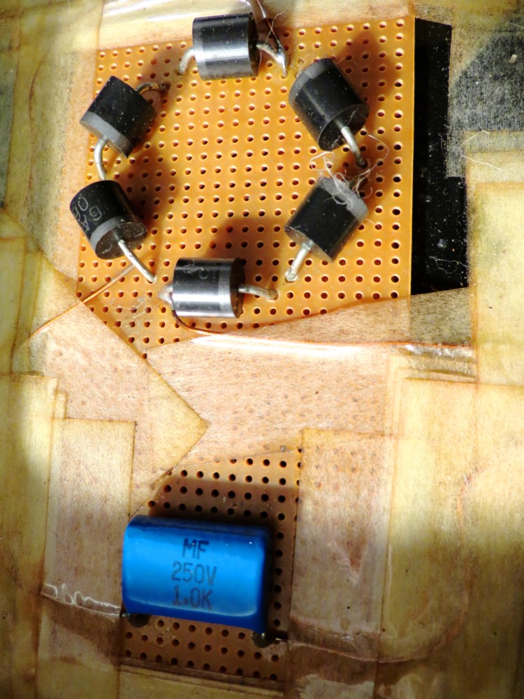
In this picture you will see that I have everything laid out just as Steven does. The knobs are very similar to his design but not exact. I couldn't find the exact knobs anywhere. The case is the same one as Steven uses. I got this one from DigiKey. The case is made by Keystone if anyone is interested. It is a very good and solidly designed case.
http://www.fileden.com/files/2006/7/30/148042/100_0251.JPG
In this picture I deviated slightly from Steven's design. I don't like to put things together with tape. So everything is either glued or bolted down. The caduceus coil was not very easy to construct. It took the better part of a day to complete. The coil itself is the required 7.8 centimeter diameter. I encased the coil in resin to hold it together. It is permanently epoxied in place. The witness well I have just recently discovered is not correct. I found someone on the web that describes the witness well as having twelve turns of wire at the bottom, six turns of wire in the middle, and twelve turns of wire at the top. So I have to redo that. I used heat shrink tubing to insulate the wire connections that go to the AC cord coming into the case. Also I made special standoffs epoxied to the case that hold the circuit board in place with screws. So nothing can move around inside the case. This was not an easy project to do. But I like to fabricate things. So this is right down my alley.
http://www.fileden.com/files/2006/7/30/148042/100_0247.JPG
In the first picture you'll notice I color coded the plugs on the electromagnet connections so that the electromagnet produces a north pole field.
http://www.fileden.com/files/2006/7/30/148042/100_0248.JPG
In the second picture I used a strain relief where the cord goes into the case. Also the cord itself was just an extension cord with a molded plug on the end. I just cut off the receptacle end and discarded it. This was cheaper this way because the extension cord was only $2.00 as opposed to $4.50 if I purchased the cord and plug separately as Steven Gibbs does with his design.
http://www.fileden.com/files/2006/7/30/148042/100_0250.JPG
In this picture you will see that I have everything laid out just as Steven does. The knobs are very similar to his design but not exact. I couldn't find the exact knobs anywhere. The case is the same one as Steven uses. I got this one from DigiKey. The case is made by Keystone if anyone is interested. It is a very good and solidly designed case.
http://www.fileden.com/files/2006/7/30/148042/100_0251.JPG
In this picture I deviated slightly from Steven's design. I don't like to put things together with tape. So everything is either glued or bolted down. The caduceus coil was not very easy to construct. It took the better part of a day to complete. The coil itself is the required 7.8 centimeter diameter. I encased the coil in resin to hold it together. It is permanently epoxied in place. The witness well I have just recently discovered is not correct. I found someone on the web that describes the witness well as having twelve turns of wire at the bottom, six turns of wire in the middle, and twelve turns of wire at the top. So I have to redo that. I used heat shrink tubing to insulate the wire connections that go to the AC cord coming into the case. Also I made special standoffs epoxied to the case that hold the circuit board in place with screws. So nothing can move around inside the case. This was not an easy project to do. But I like to fabricate things. So this is right down my alley.